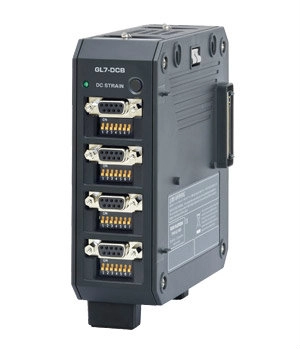
GL7-DCB
GL7-DCB specification
| Item | Description | |
|---|---|---|
| Type of module | DC bridge amplifier module - for strain gauge or sensor based on a strain gauge - | |
| Model number | GL7-DCB | |
| Number of input channels | 4 channels | |
| Input method |
All channels isolated balanced input, Simultaneous sampling, D-SUB type connector (9 pins, receptacle) |
|
| Sampling speed (interval) | 100 k Samples/s to 1 Sample/h (10 μs to 1 hr.) | |
| Built in RAM | 2 million samples for each channel | |
| Input type | Strain, Voltage, Resistance value (including potentiometer) | |
| Measurement range | Strain |
500, 1000, 2000, 5000, 10000, 20000 με (με: 10-6 strain) 0.2, 0.25, 0.4, 0.5, 1, 2, 2.5, 4, 5, 10 mV/V * Available ranges vary by the excitation voltage for the bridge. |
| Voltage | 1, 2, 5, 10, 20, 50, 100, 200, 500 mV, 1, 2, 5 V Full Scale | |
| Resistance | 1, 2, 5, 10, 20, 50, 100, 200, 500 Ω, 1, 2, 5, 10, 20, 50 kΩ Full Scale | |
| Measurement accuracy (*1) | Strain | ±(0.2% of Full Scale + 10 με) |
| Voltage | ±(0.2% of Full Scale + 10 μV) | |
| Resistance | ±0.5% of Full Scale | |
| A/D converter | Successive Approximation type, 16 bits (effective resolution: 1/40000 of the measuring full range) | |
| Input impedance | 10 MΩ ±5% | |
| Gauge ratio | 2.0 constant | |
| Supported sensor | Strain (*2) |
Strain gauge Quarter bridge (single gauge) in 2-, 3- or 4-wire (supports remote sensing in 3- or 4-wire) Half bridge (dual gauge) in 3-, 4-, 5-wire (supports remote sensing in 4- or 5-wire) Full bridge (quad gauge) in 4- or 6-wire (supports remote sensing in 6-wire) |
|
Transducer/sensor based on a strain gauge Full bridge type in 4-wire, Full bridge type in 6-wire (supports remote sensing) |
||
| Resistance | Resistor, Potentiometer | |
| Bridge resistance | 50 Ω to 10 kΩ * Available excitation power varies by selection of element. | |
| Built-in element of the bridge |
120 or 350 Ω for the quarter- and half-bridge * Available excitation power varies by selection of element. |
|
| Excitation power | Voltage mode |
1, 2, 2.5, 5, 10 V DC * Excitation voltage 5 and 10 V is available when bridge resistance is the 350 Ω or higher. |
| Current mode | Constant current: 0.1 to 20 mA (supported voltage is up to 10 V.) | |
| Zero Adjust for Strain gauge | Method | Fully automatic (via push button or setting the condition menu) |
| Max. Range | ±10,000με (με:10-6 Strain) | |
| Remote sensing | 3- or 4-wire in quarter bridge, 4- or 5-wire in half bridge, 6-wire full bridge | |
| Shunt Calibration | Approx. 60 kΩ (120 Ω gauge), Approx. 175 kΩ (350 Ω gauge) | |
| Maximum input voltage | Between (+) / (-) terminal |
10 V, Common-mode voltage: 10 Vrms AC |
| Between channels ((-) terminals) | 10 Vp-p | |
| Between channel / GND | 60 Vp-p | |
| Max. voltage (withstand) | Between channels | 1000 Vp-p (1 minute) |
| Between channel / GND | 1000 Vp-p (1 minute) | |
| Isolation | Between channel / GND | Min. 100 MΩ (at 500 V DC) |
| Common-mode rejection ratio | Min. 80 dB (50/60 Hz, Signal source impedance: Max. 300 Ω) | |
| Frequency response | DC to 20 kHz | |
| Filter | Low pass | Off, Line (1.5 Hz), 3, 6, 10, 30, 50, 60, 100, 300, 500 Hz, 1k, 3k, 5k, 10k Hz (in -30dB/oct) |
| Anti-aliasing | Off, On | |
| Support TEDS | Standard | IEEE 1451.4 Class2 (Temperate No.33) |
| Support | Reading information from the sensor and setting it to module | |
| External dimensions (W x D x H) | Approx. 49 x 136 x 160mm (Excluding Protection) | |
| Weight | Approx. 840 g | |


